
Why use an e-fuse? Part 1
This article was originally posted at EEWorldOnline.com BY
The electronic fuse is a powerful and versatile tool in the designer’s kit, but building one requires careful selection of the core amplifier; IC embodiments solve the problem.
The traditional thermal-based fuse, Figure 1, is a low-cost, widely used, well-understood, highly reliable, easy-to-apply circuit- protection component. It is available in a wide range of ratings, sizes, packages, and other factors. However, designers are always looking for new ways to meet design objectives – in this case, overcurrent protection – especially if the new way adds additional capabilities or flexibility. This FAQ will explore the electronic fuse (commonly called an e-fuse or efuse) and the characteristics of the current-sense amplifier (CSA) that is needed to make it a reality.
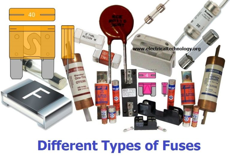
Fig 1: The well-known thermal fuse I available in a huge selection of physical sizes and package types, based on current ratings and application requirements (Image source: ElectricalTechnology.org)
Q: Bring me up to speed: what are the basics on the traditional thermal-based fuse?
A: Just see the previous FAQS: (see References 1 and 2 below).
Q: It seems like fuses are well understood, fully accepted, and can do the job; so, why are there any issues here?
A: The standard fuse has many virtues, but three of them may also be considered as restrictions: it is inflexible; it reacts relatively slowly compared to the speed and failure-sensitivity of modern circuits; and it must be physically replaced when it is activated and opens the circuit it is protecting. Further, the accuracy of such fuses at low current ratings (in the 100-mA zone) is not as high as most designers would like. E-fuses are now used in autos, hot-swap cards, and many densely packed, sensitive electric devices.
Q: What is the alternative?
A: The alternative is an all-electronic fuse which does not depend on the thermal heating and the subsequent open circuit of an inline element.
Q: What does it take to build an e-fuse?
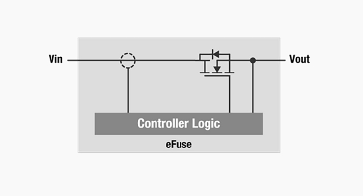
A: It takes several analog components: a precision current-sense resistor (see Reference 3; an amplifier with accurate scaling resistors for capturing and gaining-up the voltage across this resistor; a comparator circuit to “switch” at the preset value, and a FET to allow/break the path of current flow in the line being monitored, Figure 2. Note that the e-fuse has much in common with the hot swap controller and the load switch, see References 4 and 5.
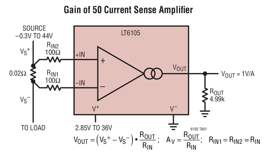
Fig 2: The voltage across the sense resistor at the front end of an e-fuse is measured by a difference amplifier which does not need either of its inputs to be referenced to ground. (Image source: Analog Devices) [Find LT6105 at DesignFast.com]
Q: How does the e-fuse work?
A: The current to be monitored passes through the sensor resistor, and the voltage across this resistor is sensed and scaled by the amplifier. Since the resistor value is known, it’s easy to use analog circuitry to set a threshold on the current passing through it using basic Ohm’s Law: I = V/R, Figure 2.
If the threshold is exceeded, the comparator which controls the FET turns the FET off, so that the current is interrupted, Figure 3. Response time is on the order of microseconds, far faster than a thermal fuse with its response time of tens and hundreds of milliseconds. Also, since the response is not dependent on thermal time constants, the element’s mass, and similar considerations, the subtleties of a thermal-fuse section are no longer issues to be considered.
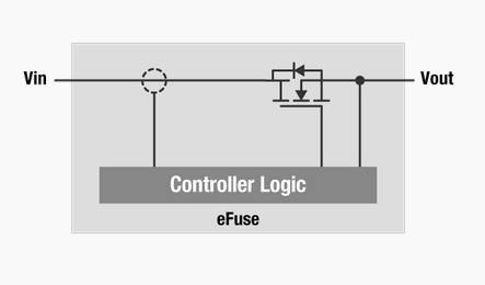
Fig 3: A FET in series with the supply line and load is used to turn the current flow on and off in an e-fuse; this FET must have very low on-resistance, so it does not induce excessive IR drop or wasted power. (Image source: Texas Instruments)
Q: What are some e-fuse considerations?
A: First, the resistor and scaling circuit must be accurate and have minimal temperature drift. Note that both changes in ambient temperature as well as unavoidable self-heating of the resistor can cause significant errors. Also, the on/off FET must be sized for the situation and may need its own gate driver, depending on its current and voltage rating.
Second, the circuit which “trips” on the overcurrent must be properly designed to not have false positive or negatives; usually, some hysteresis is added to prevent chatter. Finally, the overcurrent indication may be via a single, basic analog or the designer may decide to get “fancy” and use an ADC and processor to decide if the current threshold has been exceeded or use a digitally controlled potentiometer to allow the comparator threshold to be adjusted.
However, such complexity degrades the simplicity and reliability of the circuit. So it is critical to understand whether the overcurrent protection is just for “better” circuit performance and adaptive behavior, or for critical safety-related functions to protect other components, the power source, or even the user.
Part 2 of this FAQ will look at some aspects of the CSA, as well as the e-fuse in IC form which can eliminate the need to design and build your own.
References
- EEWorld Online, Fuses for power protection, Part 1
- EEWorld Online, Fuses for power protection, Part 2
- EEWorld Online, Options for current sensing, Part 1
- EEWorld Online, Load switches, Part 1: Basic role and principle
- EEWorld Online, Load switches, Part 2: IC implementations and benefits
- EEWorld Online, Programmable electronic fuse sustains 4 A over 8 to 48-V range
- EEWorld Online, Fuses that blow safely
- Analog Devices, LTC1153 Auto-Reset Electronic Circuit Breaker Data Sheet
- ST Microelectronics, STEF01 8 V to 48 V Universal Electronic Fuse Data Sheet
- Texas Instruments, PS25925x, TPS25926x Simple 5-V/12-V eFuse Protection Switches